Choosing the right Butterfly Valve With Bypass requires more than comparing prices, sizes, or brand names. The bypass arrangement can influence startup control, pressure equalization, maintenance access, and overall plant reliability. A practical buying decision begins with the medium, operating temperature, pressure range, pipe diameter, and required flow direction.
Industrial valve specialist Dr. Elena Marquez explains, “A bypass is not decoration; it is a controlled path for pressure equalization and safer operation.” Her observation highlights a common purchasing mistake. Some buyers focus on the butterfly disc and overlook the bypass valve, actuator, seals, and connection layout. That oversight can create difficult access around a crowded pipeline. It may also complicate isolation during inspection.
This 2026 buying guide examines common Butterfly Valve With Bypass types, including manual, pneumatic, electric, and integrated bypass configurations. It considers resilient-seated and metal-seated designs, wafer and lug bodies, and materials such as ductile iron, stainless steel, and carbon steel. Each option behaves differently when exposed to abrasive slurry, corrosive chemicals, steam, or treated water.
Look closely at the details.
A reliable specification should identify flange standards, seat compatibility, torque requirements, leakage class, actuator protection, and spare-part availability. Field experience also matters. A valve that performs well in a clean test line may struggle when sediment settles around the disc. No selection is perfect. However, careful comparison can reduce unexpected downtime and improve long-term operating confidence.
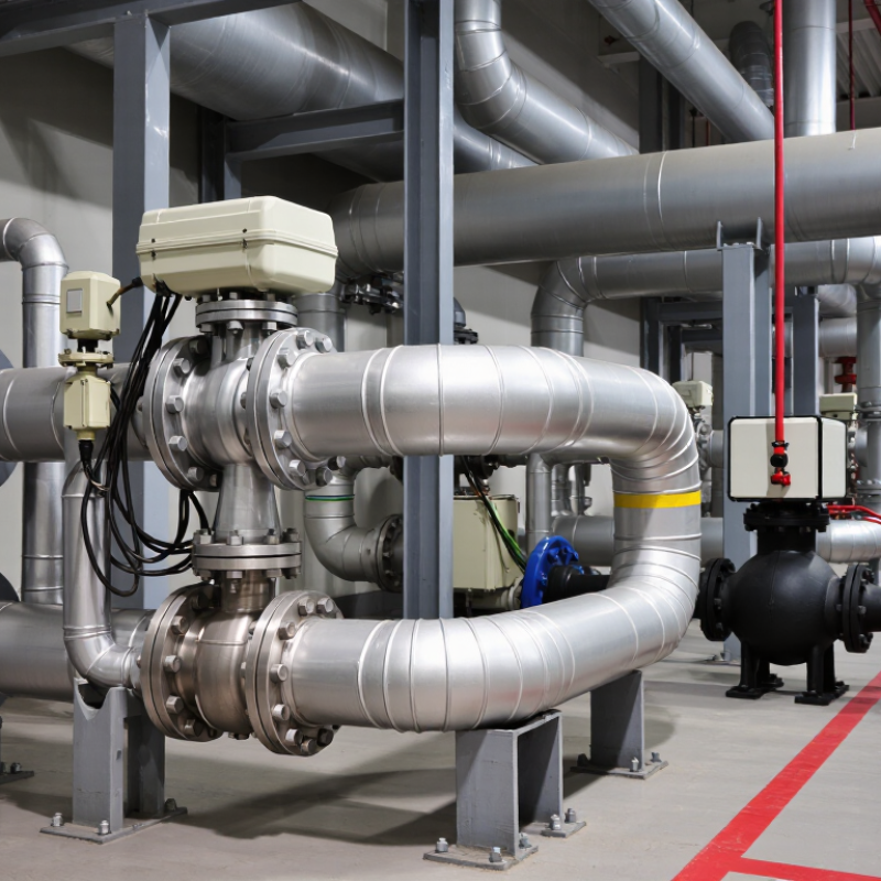
A butterfly valve with bypass combines a primary butterfly valve with a smaller parallel pipe and one or more auxiliary valves. The bypass route helps equalize pressure across the main disc before opening. This design is useful in chilled-water lines, process piping, and large-diameter systems where sudden pressure changes can stress equipment.
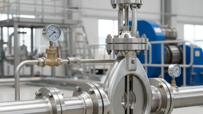
Its structure is simple but requires careful coordination. The main valve contains a disc, stem, body, and resilient or metal seat. The bypass assembly normally includes a smaller valve, connecting pipe, and isolation points. Pressure gauges can improve control. During operation, the main valve stays closed while the bypass opens gradually. Fluid then moves through the smaller route, reducing the pressure difference. The operator opens the main valve after pressure becomes nearly balanced. The bypass closes afterward.
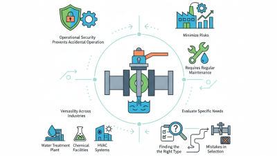
Small details matter. Select body and seat materials for the actual fluid, temperature, and pressure. Check the required leakage class, flange standard, actuator torque, and fail position. A bypass is not automatically a maintenance solution. The line still needs isolation, drainage, and safe access. Field inspections often reveal another issue: bypass piping can be undersized, making equalization painfully slow. I would request flow calculations and pressure-test records before approval. No selection is perfect. Corrosion, dirty fluid, or incorrect actuator sizing can still cause sticking, even when the valve appears suitable on paper.
Bypass arrangements allow flow, pressure equalization, warm-up, or minimum-flow protection while the main butterfly valve is closed or being operated. The chart uses a functional comparison: 1 means the function is a primary purpose of the bypass arrangement, while 0 means it is not the defining purpose.
When selecting a butterfly valve with bypass, match the arrangement to the operating objective, then verify pressure class, temperature, fluid compatibility, actuator requirements, and required bypass flow capacity for the specific system.
2026 Top Butterfly Valve With Bypass Types Buying Guide
Main Bypass Configurations and Their Functional Differences
A butterfly valve with a bypass reduces pressure differences before the main disc opens. This protects seats, shafts, and connected equipment during startup. The integral bypass sits inside the valve body or its compact assembly. It saves space and keeps the flow path short. However, inspection can be difficult when access is limited.
An external parallel bypass uses separate piping, a small valve, and isolation points. Operators can open it gradually, equalizing pressure across the main butterfly valve. This design supports larger pipelines and easier maintenance. It also needs more installation space and additional leak points. An automatic bypass may use an actuator, pressure sensor, or control logic. It offers consistent operation, but poor calibration can cause delayed opening or unnecessary cycling. Simple is not always safer.
Tips: Check the pressure rating, temperature range, seat material, and required equalizing time. Ask whether the bypass must remain operable during maintenance. Review valve orientation and drainage, especially in lines carrying dirty or wet fluids. A bypass that is too small may equalize pressure slowly. A bypass that is too large can create sudden flow and vibration. Confirm interlocks before purchase. A tidy specification sheet can still hide a weak control sequence.
| Bypass configuration | Typical arrangement | Primary function | Flow and pressure behavior | Control method | Main advantages | Main limitations | Best-fit applications |
|---|---|---|---|---|---|---|---|
| Manual parallel bypass | A small isolation valve and a small bypass line installed parallel to the main butterfly valve. | Equalizes pressure across the main disc before opening or closing the large valve. | The bypass provides a low-flow path for gradual pressure equalization; the main valve carries normal operating flow. | Operator-controlled hand valve, usually with a separate sequence procedure. | Simple design, low purchase cost, easy visual inspection, and limited auxiliary equipment. | Dependent on operator timing; incorrect sequencing can cause water hammer, torque spikes, or seat damage. | Water pipelines, utility systems, fire-water networks, and applications with infrequent operation. |
| Automatic pressure-equalizing bypass | A parallel bypass fitted with an actuated valve, pressure-sensing devices, or an interlocked operating sequence. | Automatically reduces the differential pressure before the main butterfly valve is moved. | Controlled bypass flow increases gradually and closes after the main valve reaches the required position. | Electric, pneumatic, or hydraulic actuator with limit switches and control logic. | Improves repeatability, reduces operator error, and supports remote or unmanned operation. | Higher installation cost, more components to maintain, and dependence on instrumentation or power. | Large-diameter process lines, pumping stations, power facilities, and critical water systems. |
| External bypass station | A separate, accessible bypass assembly located beside the main valve, often including isolation, throttling, check, and pressure-relief components. | Maintains controlled service continuity or equalizes pressure while the main valve is isolated. | Bypass capacity can be sized independently from the main valve for controlled filling, draining, warming, or low-flow operation. | Manual or automated, depending on the required operating sequence. | Flexible layout, convenient maintenance access, and easier replacement or upgrade of bypass components. | Requires additional space, piping, supports, and pressure-loss assessment. | Large pipelines, turbine or pump isolation, district-energy systems, and maintenance-sensitive installations. |
| Integrated valve bypass | The bypass passage and smaller valve are built into or packaged with the main valve assembly. | Provides pressure balancing without a fully separate field-installed bypass line. | The restricted internal passage limits bypass flow and is intended mainly for equalization rather than full-capacity service. | Usually manual; actuator options depend on the valve design and service requirements. | Compact footprint, fewer external joints, and faster installation where space is limited. | Internal access can be difficult; bypass capacity and repair options may be limited. | Packaged skids, compact mechanical rooms, and systems requiring a factory-assembled solution. |
| Three-valve bypass arrangement | A bypass line with upstream and downstream isolation valves plus a central throttling or control valve. | Allows the bypass to be isolated, throttled, drained, or serviced while preserving clear operating control. | The central valve regulates pressure and flow; the end valves provide positive isolation for maintenance. | Manual, automated, or combined manual-automatic operation. | Good maintainability, clear isolation boundaries, and better control than a simple open-or-close bypass. | More valves, more potential leak points, and a greater need for correct operating procedures. | High-value process systems, steam or hot-water services, and installations requiring bypass maintenance. |
| Check-valve-assisted bypass | A bypass line incorporating a non-return valve, often combined with a manual or actuated isolation valve. | Prevents reverse flow through the bypass and protects the line from unintended circulation. | Permits flow only in the designed direction; cracking pressure and flow resistance must be included in calculations. | Passive check action with optional manual or automated isolation. | Reduces reverse-flow risk and can support pressure equalization in systems with changing pressure conditions. | Check valves can stick, chatter, or create additional pressure loss if incorrectly sized or installed. | Pump discharge lines, water-transfer systems, and piping where reverse flow is unacceptable. |
| Control-valve bypass | A smaller control valve installed parallel to the main butterfly valve to provide metered low-flow operation. | Maintains a controlled minimum flow or gradual startup when the main valve is closed or partially open. | Provides finer flow regulation than a simple isolation bypass, but creates a permanent controlled-flow pressure drop. | Typically pneumatic or electric modulating control, with position feedback where required. | Supports stable startup, minimum-flow protection, and process control in variable-demand systems. | More expensive and complex; throttling may cause noise, vibration, cavitation, or erosion if poorly selected. | Pump protection, thermal systems, process utilities, and services requiring continuous low-flow control. |
| Temporary commissioning bypass | A temporary parallel pipe and valve assembly used during flushing, testing, startup, or staged commissioning. | Maintains temporary circulation or permits system cleaning before the main butterfly valve is placed into service. | Flow capacity is selected for the commissioning task rather than normal continuous operation. | Usually manually operated and removed or permanently isolated after commissioning. | Useful for project startup, line cleaning, pressure testing, and staged plant operation. | Not normally intended for permanent service; temporary supports, isolation, and documentation are essential. | New pipelines, plant expansions, replacement projects, and systems requiring staged startup. |
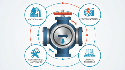
A 2024 Grand View Research report valued the global industrial valve market at about US$78 billion in 2023. Water treatment, energy, and process industries remain major demand areas. That scale makes specification discipline essential. For a butterfly valve with bypass, compare nominal diameter, pressure class, temperature range, and flow coefficient, or Cv. Check whether the stated Cv uses water, full opening, and stable upstream pressure. Small details matter.
The bypass type changes the operating risk. A parallel bypass can equalize pressure before the main disc opens. A small balancing line may reduce actuator torque, but it can restrict flushing. A manual bypass suits occasional use. An automated bypass improves sequencing but adds control points and failure modes. Specify body, disc, stem, and seat materials against the actual fluid. Confirm shaft torque at the lowest temperature, not only at room temperature. That mistake is common.
Use API 609 for butterfly valve design categories, ISO 5752 for face-to-face dimensions, and ISO 5211 for actuator interfaces. EN 12266-1 supports pressure testing and leakage assessment. A 2024 MarketsandMarkets analysis identifies water, power, and oil and gas among key industrial valve application sectors. Still, market reports cannot replace site data. I would request verified test curves, cycle history, and allowable leakage limits. Published figures can look precise. They are not always comparable. Include access space, bypass isolation, drain points, and emergency manual operation before selecting the final type.
2026 Top Butterfly Valve With Bypass Types Buying Guide: How to Select the Right Valve for Pressure, Media, and Pipeline Conditions
A butterfly valve with bypass can ease startup, balancing, and maintenance in demanding pipelines. Selection starts with pressure, not price. Check the maximum working pressure, pressure surges, temperature range, and required shutoff class. A valve rated for normal pressure may fail during pump starts. Leave a practical safety margin.
Media changes the decision. Clean water may suit resilient seating, while abrasive slurry needs stronger disc and seat materials. Corrosive chemicals require verified compatibility for the body, shaft, liner, and seals. Do not judge compatibility from the fluid name alone. Concentration and temperature can change everything. I have seen otherwise sound valves suffer because one small elastomer was overlooked.
Pipeline conditions also matter. Measure line size, flange standard, face-to-face length, flow direction, and available actuator space. A bypass may use a smaller valve, but its pressure drop still needs calculation. Consider manual, pneumatic, or electric operation, along with fail-safe needs and access for inspection. Confirm the bypass arrangement supports isolation without trapping unsafe pressure. That detail is easy to miss. Review test certificates, material traceability, and applicable local standards before purchase. Field conditions rarely match the drawing perfectly, so verify measurements on site.
Choosing a butterfly valve with a bypass requires more than comparing purchase prices. The bypass should match the main line’s pressure, temperature, and flow requirements. A smaller bypass can equalize pressure before opening the primary valve. This reduces operating force and protects the disc and seat. For isolation service, verify that the valve closes tightly under the actual system pressure. Soft seats may suit clean water, while abrasive or hot media require more durable materials.
Installation quality strongly affects lifecycle cost. Keep the valve centered between flanges, and prevent gasket material from entering the pipeline. Check disc clearance before applying full torque. Do not use the actuator to correct poor alignment. That shortcut often causes early leakage. Install accessible isolation points around the bypass, then label flow direction and operating positions clearly. Safety depends on lockout procedures, pressure release, and confirming zero energy before maintenance. A bypass is not a substitute for isolation.
Maintenance should include visual checks, bolt inspection, actuator testing, and periodic leak verification. Record operating cycles, repairs, and unusual resistance. These records support reliable replacement planning. A low-cost valve may become expensive when seat wear, shutdown labor, and spare parts are included. Calculate energy use and expected service life, not only the invoice price. Some assumptions will be wrong. Review them after the first operating season, especially when the medium, temperature, or cycling pattern changes.