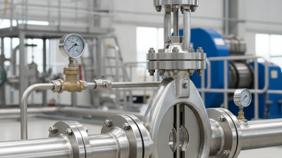
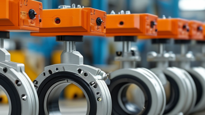
Choosing a Dry Shaft Butterfly Valve in 2026 requires more than comparing purchase prices. The right selection must match the medium, pressure, temperature, operating cycle, and installation environment. A valve handling treated water faces different demands from one controlling abrasive slurry or corrosive chemicals. Small details matter. Shaft sealing, disc clearance, actuator torque, and gasket compatibility can determine years of reliable service.
Recent forecasts from Grand View Research and MarketsandMarkets indicate continued growth in the global butterfly-valve market through 2030. However, their estimates differ because each report uses different product definitions and regional assumptions. That difference deserves attention. Market growth does not automatically prove that every valve design suits every application. The International Organization for Standardization, API 609, and AWWA C504 provide useful reference points for dimensions, performance, and testing. Buyers should verify which standard applies to their system, rather than accepting a supplier’s general claim.
Field experience often reveals what catalog pages miss. A dry shaft design can reduce exposure between the shaft and process fluid, but it still requires correct packing, bearing support, and alignment. Inspectors should look for documented pressure tests, material certificates, cycle ratings, and traceable quality records. A valve installed beside a vibrating pump may need stronger support than the same model installed on a quiet pipeline. The final decision should balance lifecycle cost, maintenance access, safety, and verified performance. The cheapest option may become expensive after one failed shutdown.
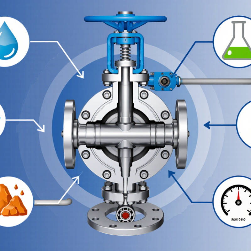
A dry-shaft butterfly valve is designed to limit process fluid from traveling along the shaft toward external bearings or an actuator. Sealing elements around the shaft help create this barrier, while the disc still turns inside the pipeline. “Dry shaft” describes a design feature; it is not, by itself, an API 609 valve category.
Details vary, so review the construction drawing and confirm the intended service conditions.
API 609 classifies butterfly valves as Category A or Category B. Category A generally covers concentric designs, where the disc and shaft align with the seat’s centerline. Category B generally covers offset designs, which can reduce seat contact during operation.
The standard also addresses design, materials, dimensions, and pressure-temperature considerations.
Do not infer a valve’s category from its appearance alone. Check the applicable API 609 edition, product data, and manufacturer’s documentation.
Tips: Verify the shaft-seal arrangement and pressure rating. Check media compatibility, temperature, and cycle frequency. Ask whether the stated API 609 category applies to the complete valve. Small details matter. A datasheet may leave something unclear; request clarification before specifying the valve.
How to Choose a Dry Shaft Butterfly Valve in 2026
Match the valve’s pressure rating to the highest pressure it will actually face, including surges. PN10 and PN16 indicate nominal pressure classes in bar under specified reference conditions; they do not guarantee that pressure at every temperature. Class 150 is a separate rating system, not an automatic equivalent to PN16. Check the applicable pressure-temperature tables for the exact valve body, disc, seat, and materials. Small details matter. A hot-water line may need a lower allowable pressure than a cool-water line.
Review the operating range, not just the normal set point. Record startup temperature, cleaning cycles, pressure spikes, and the fluid’s compatibility with seat materials. For example, a valve seeing 12 bar at ambient temperature may be unsuitable if the line also runs hot. Confirm flange drilling and dimensions against the piping standard, too. A rating mismatch can cause leakage or shorten service life. The datasheet may not cover every real-world condition, so ask the supplier for written confirmation when limits are close.
Tips: Compare the pressure-temperature chart with your maximum operating conditions, then leave a practical margin for transients. Verify the complete valve assembly rating, not the actuator rating alone. If the duty cycle or fluid data is uncertain, pause before selecting; a neat rating label cannot replace missing process information.
| Selection factor | PN10 | PN16 | Class 150 | What to check before selection |
|---|---|---|---|---|
| Rating system | Metric nominal pressure designation under applicable EN flange standards. | Metric nominal pressure designation under applicable EN flange standards. | ASME pressure class; allowable pressure depends on material and temperature under the applicable ASME standard. | Confirm the valve, flanges, drilling pattern, and mating piping use compatible standards. PN and Class designations are not direct equivalents. |
| Nominal pressure reference | 10 bar nominal designation. | 16 bar nominal designation. | Not a fixed pressure in bar. For example, ASME B16.5 Class 150 carbon-steel flanges are rated at about 19.6 bar at temperatures from −29°C to 38°C; the allowable pressure decreases as temperature rises. | Use the pressure–temperature table for the exact body material and applicable standard. The valve’s own rating may be lower than its flange rating. |
| Typical choice by operating pressure | Consider for services whose maximum design pressure, including transients, remains within the valve’s temperature-adjusted rating. | Consider when the design pressure is above the suitable PN10 rating but remains within the valve’s temperature-adjusted rating. | Consider for ASME-system piping when the valve and end connections are specifically rated for the design conditions. | Include pump shutoff pressure, surge, water hammer, vacuum conditions, and other credible pressure excursions in the design case. |
| Temperature and seat material | Pressure capacity and service temperature depend on the valve construction and seat material. EPDM, NBR, and PTFE have different chemical compatibility and temperature limits; no single limit applies to every formulation or valve design. | Check the supplier’s pressure–temperature chart and chemical compatibility data for the actual fluid. Do not assume the seat’s temperature limit is the same as the body’s. | ||
| Dry-shaft configuration | A dry-shaft design isolates the shaft from the process fluid using the valve’s sealing arrangement; construction details vary by design. | Verify shaft sealing, bearing arrangement, leakage requirements, orientation, and suitability for the fluid, operating cycle, and maintenance plan. | ||
| End connections and fit | Match the valve’s PN10 flange pattern and face-to-face dimensions to the piping specification. | Match the valve’s PN16 flange pattern and face-to-face dimensions to the piping specification. | Match the specified ASME class, flange dimensions, facing, and face-to-face dimensions. | Check DN/NPS size, wafer or lug style, bolt pattern, disc clearance, and whether the valve is suitable for dead-end service where required. |
| Practical selection rule | Select the rating only after establishing maximum design pressure and temperature, then verify the complete valve assembly against its documented pressure–temperature limits. | Allow for applicable design requirements and operating margin; obtain certified data for the exact model, size, materials, and end connection. | ||
How to Choose a Dry Shaft Butterfly Valve in 2026
A dry shaft butterfly valve keeps the stem area isolated from the process fluid. The seat still determines whether the valve survives. Start with the actual media, temperature, pressure, concentration, and cycling frequency. Do not guess. A clean water line and a chemical wash line may look similar, yet require different elastomers.
EPDM suits water, dilute acids, alkalis, and many polar chemicals. It performs poorly with petroleum oils, fuels, and hydrocarbon-based fluids. NBR is often a better choice for oils, lubricants, and fuel-related service. However, it has weaker resistance to ozone, weathering, and some aggressive chemicals. Temperature changes everything. Check both continuous and short-term limits, not just the normal operating temperature.
PTFE offers broad chemical resistance and a low-friction sealing surface. It is useful for corrosive media, but pressure cycling may cause creep or cold flow. Metal seats handle higher temperatures, abrasive particles, and demanding mechanical service. They usually need tighter machining and careful alignment. Shutoff may not equal that of a soft seat. In field selection, I would also review particle size, seat wear, and cleaning methods. A valve can be chemically compatible yet fail early from abrasion. I once treated temperature as the main variable; that was too simple. Media concentration and cycling often mattered more. Request test data, inspect the valve’s seat design, and compare it with the real operating pattern.
Seat Material Screening by Media Type
Screening guide only: 2 = generally suitable, 1 = conditional, 0 = generally unsuitable. EPDM is often selected for water and dilute acids but is generally unsuitable for mineral oils; NBR commonly suits oils but is less suitable for many acids. PTFE has broad chemical resistance, while metal-seat suitability depends on the alloy, process conditions, and valve design. Confirm compatibility with the valve manufacturer for the exact medium, concentration, temperature, and pressure.
For a dry shaft butterfly valve, actuator sizing should start with breakaway torque: the force needed to move the disc from its seated position. This can exceed running torque, especially after long idle periods or when the seat presses firmly against the disc. Check the valve’s torque data for your pressure differential, temperature, and service conditions. Then size the actuator to deliver at least 125% of the required breakaway torque. That extra 25% provides a practical margin, not a substitute for accurate operating data. Small details matter.
Confirm the actuator can provide that output at the actual supply pressure and throughout its stroke. A unit that meets the torque figure only at peak pressure may struggle during a pressure dip. For example, a valve exposed to a 6-bar differential may need more starting force than the same valve under a lighter load. Account for cycling frequency, seat wear, and any expected changes in temperature. I have seen clean calculations miss one awkward condition: a valve sitting unused for weeks. Recheck the assumptions.
Tips: Ask for breakaway and running torque values, not just a single rating. Verify the actuator’s output curve, supply pressure, and safety margin together. Record the operating conditions; estimates can drift.
How to Choose a Dry Shaft Butterfly Valve in 2026
A dry shaft butterfly valve should begin with documented leakage performance, not a low purchase price. Ask for an ISO 5208 test report showing Rate A at the required pressure and temperature. Rate A normally means no visible leakage during the specified test. However, test conditions matter. Confirm the pressure direction, medium, duration, and valve size. A report without these details is incomplete. In field inspections, small documentation gaps often become costly installation delays.
Check the ISO 5752 face-to-face dimension before approving the valve. Match the listed series and nominal size with the existing pipeline layout. A few millimeters can affect flange alignment, gasket compression, and actuator clearance. Measure twice. Also verify the dry shaft design, stem sealing, disc material, and shaft retention method. These details influence maintenance access and long-term reliability. I would not rely on the phrase “maintenance-free” without service records or a clear inspection procedure.
Certification should be traceable to the exact valve configuration. Review material certificates, pressure-test records, dimensional drawings, and applicable conformity documents. The certificate should identify the size, pressure rating, materials, and test standard. Check whether the documents cover the assembled valve, rather than separate components only. Requirements vary by installation location and service. That part is easy to overlook. A technically correct valve can still be unsuitable if its certificates do not match the project’s approval process. Keep the uncertainty visible, and ask for clarification before ordering.