A Rigid Type Dismantling Joint can make a difficult maintenance task more manageable. Installed beside a valve, pump, or meter, it provides adjustment space when pipework is assembled or equipment needs removal. Its rigid construction helps maintain a fixed connection, while tie rods on many designs control movement. Details vary by manufacturer, so the product drawing matters.
For a practical framing, this introduction uses an illustrative expert voice, not a verified quotation. Pipeline engineer Thomas Reed puts the point this way: “Plan for removal before the valve needs repair.” That is the central question behind choosing a Rigid Type Dismantling Joint: does its adjustment range, pressure rating, material, and flange drilling match the actual system? Check the adjacent pipe supports and restraint design, too. A joint is not a substitute for sound anchoring. Small oversights can become awkward on site; even a few millimeters of misalignment may complicate installation. The sections ahead examine where rigid designs fit, what to verify before purchase, and which limitations deserve honest attention. Not every pipeline needs one.
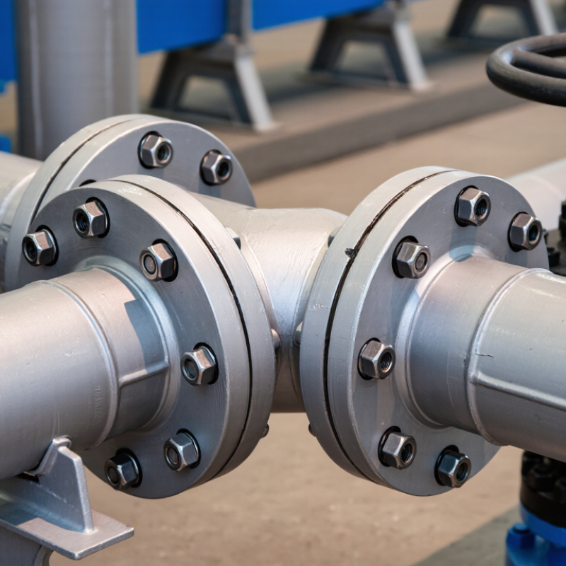
A rigid type dismantling joint is a flanged fitting that creates a controlled gap in a pipe run. It helps installers connect or remove equipment such as valves, pumps, and flow meters without shifting long sections of pipe. It is rigid in service, not a flexible expansion joint. That distinction matters.
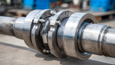
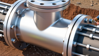
Typical components include a central sleeve, end rings or flange adaptors, a sealing gasket, and tie rods with nuts. The end adaptors connect to the pipe or equipment flanges. The sleeve bridges the joint, while the gasket seals the waterway. Tie rods hold the assembly together and transfer axial forces. Exact layouts vary by design, so check the supplied drawings before installation.
During fitting, installers adjust the joint’s length to align bolt holes and close the gap between flanges. Once aligned, they tighten the flange bolts and tie rods in the specified sequence and to the specified torque. The joint then provides a sealed, restrained connection. It does not compensate for ongoing pipe movement. Small alignment errors can still cause leaks; I would not treat adjustment as a substitute for accurate pipe support. When maintenance is needed, loosening the assembly creates clearance to withdraw the connected component.
Why Choose a Rigid Type Dismantling Joint?
How PN10 and PN16 Pressure Classes Relate to EN 1092-2 Flanges
PN10 and PN16 identify nominal pressure classes: commonly 10 bar and 16 bar. They are not guaranteed working limits under every condition. EN 1092-2 provides dimensional tables for cast-iron flanges, including bolt patterns for these classes. Check the specified DN, pressure class, and flange drilling before ordering. A PN16 joint fitted between PN10 flanges may not match their bolt pattern, even if the pipe diameter looks right.
Details matter. Compare the dismantling joint’s flange dimensions with the adjoining flanges, then confirm the system’s design pressure, temperature, and materials. The pressure rating of the complete assembly is limited by its lowest-rated component. EN 1092-2 is the dimensional reference; the manufacturer’s technical data should confirm the joint’s permitted service conditions. A rigid type joint can simplify removal by providing axial adjustment during installation. It does not replace proper pipe support or accommodate unrestricted movement. A few millimetres matter. It is easy to focus on PN numbers and overlook gasket seating or bolt length; that is worth a second check.
PN10 and PN16 flange pressure designations under EN 1092-2
PN10 and PN16 indicate nominal pressure classes of 10 bar and 16 bar respectively. For a rigid dismantling joint, confirm that its flange drilling matches the pipe flange’s DN and PN requirements under EN 1092-2. The PN designation alone does not establish the allowable working pressure in every service condition; check the component specifications, materials, and operating temperature.
A rigid-type dismantling joint provides controlled axial adjustment between flanged pipework. That travel helps installers bring bolt holes into line without forcing the valve or adjacent pipe into position. In practice, alignment is rarely perfect. A few millimetres can make the difference between a clean fit and bolts that resist tightening.
Small movement matters.
During valve replacement, the joint can be shortened within its rated adjustment range to create working clearance. This can make it easier to remove a heavy valve without shifting long pipe sections.
Before loosening connections, isolate and drain the line, support the valve and pipework, and follow the joint’s installation instructions. The joint is not a substitute for proper pipe supports. Check its permitted travel, flange dimensions, and tie-rod settings; these vary by design.
One awkward detail is easy to miss: adjustment helps with fit-up, but it cannot correct major misalignment. Take measurements before tightening, and recheck the flange faces after the assembly is supported.
Why Choose a Rigid Type Dismantling Joint?
What Tie Rods Do to Restrain Pressure Thrust in Piping Systems
Pressure inside a pipe pushes against fittings and joints, creating axial thrust. A rigid dismantling joint uses tie rods to resist this force across the joint. Under pressure, the rods carry tension and help prevent the joint from pulling apart. The load does not disappear; it transfers through the rods and connected components into the piping system’s supports. That detail matters. Tie rods must be sized for the expected pressure, pipe diameter, and operating conditions.
Tips: Check rod size, position, and tightening against the joint’s technical specifications. Confirm that nearby flanges, anchors, and supports can take the transferred load. A quick visual check is useful, but it cannot replace proper engineering review.
A rigid joint can also make installation and later removal more manageable, especially where equipment needs periodic access. Still, tie rods are not a cure-all. They do not automatically replace correctly designed anchors or guides, and poor installation can leave loads unevenly distributed. I would avoid assuming that a joint is restrained just because rods are visible. Verify the design, inspect the connections, and consider pressure surges as well as steady operating pressure. Small details can become costly surprises.
| Topic | Engineering detail | Why it matters |
|---|---|---|
| Primary purpose | A rigid type dismantling joint provides an adjustable-length connection that can simplify installation and removal of flanged equipment, valves, or pipe sections. | The adjustment can help accommodate installation tolerances and provide clearance for maintenance, subject to the joint’s design and installation instructions. |
| Role of tie rods | Tie rods connect the joint’s end components and act in tension to limit axial separation when the assembly is exposed to pressure thrust. | They help restrain the joint assembly; the rods, nuts, end components, and connected structure must all be suitable for the calculated loads. |
| Pressure-thrust relationship | A simplified estimate is F = P × A, where F is axial force, P is internal pressure, and A is the relevant effective area. | Use the effective pressure area specified or confirmed by the joint design—not automatically the pipe’s nominal bore area. |
| Illustrative thrust calculation | For an illustrative effective diameter of 300 mm and pressure of 1.0 MPa: area ≈ 0.0707 m²; estimated thrust ≈ 70.7 kN. | This is a simplified example only. Actual thrust depends on the joint’s effective area, operating and test conditions, and system configuration. |
| Illustrative tie-rod load sharing | If four rods shared the example’s 70.7 kN thrust equally, the average axial load would be about 17.7 kN per rod. | Equal sharing is an idealized assumption, not a rod-selection value. Design must consider load distribution, safety factors, material strength, connections, and applicable codes. |
| Restraint limits | Tie rods restrain axial movement within their intended design limits; they do not automatically provide support for pipe weight, control lateral movement, or replace engineered anchors and guides. | Coordinate the joint with the piping layout and the thrust-resisting system. Verify which components are designed to carry each load. |
| Installation checks | Confirm joint travel and permitted setting, flange alignment, gasket compatibility, fastener requirements, and tie-rod arrangement against the approved drawings and installation instructions. | Correct fit-up and assembly help avoid unintended loads and ensure the joint performs within its specified operating envelope. |
| Design verification | Check the design pressure, temperature, fluid, transient or surge conditions, effective thrust area, rod and connection capacity, and loads on adjacent piping and supports. | Have a qualified piping engineer verify the complete load path and applicable project requirements before specifying or installing the joint. |
Note: Numerical values above are illustrative calculations, not product ratings or design recommendations.
Why Choose a Rigid Type Dismantling Joint?
How to Select a Joint by DN Size, Pressure Rating, and Pipe Material
Selecting a rigid dismantling joint starts with the pipe, not the catalogue. Confirm the DN size and measure the pipe’s actual outside diameter. DN is a nominal designation, so pipes with the same DN can have different outside diameters under different standards. Check flange dimensions and drilling too. A small mismatch can make installation difficult.
Match the joint’s pressure rating to the system’s maximum operating pressure, including foreseeable surges. Check the rating at the expected temperature, and confirm that connected flanges, bolts, and gaskets are suitable. Do not guess. A joint’s stated rating does not automatically cover every part of the assembly. For critical lines, have a qualified engineer review the design conditions.
Pipe material matters. Steel, ductile iron, PVC, and other materials may need different adaptors, restraint arrangements, or gasket compounds. Consider the fluid, temperature, corrosion exposure, and coating compatibility. Verify how the joint transfers loads; not every dismantling joint provides the same restraint. The adjustment length should also leave enough room for removal without forcing the pipework. It’s easy to overlook that detail. Record the pipe standard, measured dimensions, pressure conditions, and material before ordering, then confirm them against the manufacturer’s technical drawing.